SAFTY WARNING! Pay careful attention to wiring the cold start injector. If done incorrectly, it is possible
to accidentally connect the power wire directly to the starter. As a precaution, put the car in Neutral and set the parking brake so in case this happens you prevent the car from unexpectedly lurching
forward or backward (potentially over top of you!).
- Take inventory. You should have the following parts: (1) Grunt Box (GB) (1) power wire with fuse holder (1) 10A fuse (in holder). I no longer include the following as they were a pain to keep on hand and you can source them easily and cheaply; (2) ring terminals (4) butt connectors (3) Scotchlok "vampire" connectors
- Remove the following; negative and positive cables from battery, intercooler (to help with wire routing), trunk trim on engine firewall side
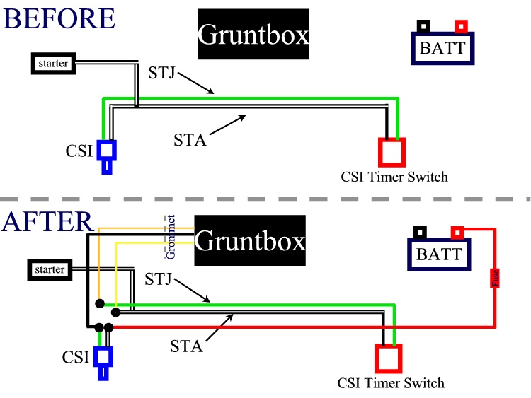
- Place the Grunt Box (GB) and the attached wires on the trunk floor. Feed the Cold Start Injector (CSI) drive wire (4' Black), the STA sense wire (Yellow), and the STJ sense wire (Orange or Red) through the engine bay. The best way to do this is to use the existing ECU harness grommet. You can poke a hole in the rubber bladder portion with a nail and feed the 3 wires through. The rubber will retract and conform around the added wires. It is very similar to this reference .
- Remove the connector from the cold start injector. You can use a small flat-head screwdriver to release the C clip. Don't lose the clip!
- Cut the connector from the harness in the middle of the available slack. Cut back enough of the plastic cover to strip about 1/4" of the wires.
- With the supplied butt connectors, connect the following wires from the Grunt Box to the harness side of the CSI connector wires; Orange(or Red) to Green and Yellow to Black-White.
- Strip the two wires from the cold start injector connector. With a supplied butt connector, connect the GB CSI control wire (4' Black) CSI connector's Green wire. On the Black-White connector wire, connect one end of the separate Red power cable, and on the other end crimp the yellow ring connector. Leave the CSI connector disconnected until later after step 15..
- Neatly harness the 4 wires you've connected (wire ties work nice), and route them all back to the grommet together. If there is slack in any of the 3 wires coming from the GB, pull it into the trunk. Route the fat red wire along the back of the engine compartment, and then forward along the left side and up to the battery. Use wire ties or electrical tape to secure it at suitable points along the run. Attach the ring terminal to the bolt on the positive battery terminal. Neatly harness any excess slack in the wire.
- Reinstall the intercooler. You're done in the engine bay for now.
- Find a suitable spot to mount your GB on the front surface of the trunk (the same one the factory ECU is on). Next to the ECU somewhere would be nice. Mount it using good double-sided tape (not included) or other clever means. A few early GBs had a metal screw exposed on the outside of the box. That screw is HOT (+13V). Take care to keep this from contacting chassis ground!!! Some tape over it for insulation would be effective and appropriate.
- You will now make 3 splice connections to the factory ECU
wiring using Scotlok ("vampire") connectors. We will be
tapping into the Vbat, IGT, and VTA signals using these connectors. The
3 wires from the GB will most likely be stripped at the end from
testing. If they are, cut off the stripped portion.
The instructions for using these connectors are in this datasheet .
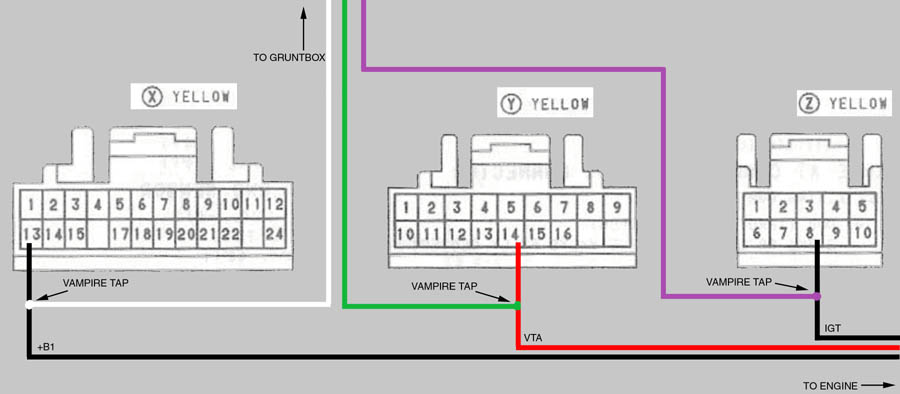
There are 3 ECU connectors, labeled by Toyota as X, Y and Z.
There will be 1 wire to splice in each connector. The diagram below
shows how to connect these wires. THE PIN NUMBERS ARE REFERENCED AS LOOKING AT THE PIN SIDE OF THE CONNECTOR (*NOT* THE WIRED SIDE

- Connect the following wires from the ECU connectors to the GB wires: [IGT signal] Z-8 (Black) to GB (Purple); [+B1 signal] X-13 (Black) to GB (White); [VTA signal] Y-14 (Red) to GB (Green)
- Crimp the included blue ring connector to the ground wire (short Black). Connect the ground to a clean, solid ground point as close to the GB as possible. Ideal is one of the mounting bolts for the ECU to attach this wire.
- Re install the trunk trim. Re connect the battery cables.
- Test drive and run the car until the ECU re-learns the lean condition, which is usually between 30-100 miles. You should be able to notice the change in drivability when this happens Keep in mind that with the cold start injector disconnected, the engine may be difficult to start when cold.
- Reconnect the cold start injector connector and enjoy the grunt!
NOTE: As of 8/31/16 the STJ sense wire changed color from Orange to Red. The instructions have been updated, but the picture below has not.